版本:Ubuntu22.04
首先安装cartographer的humble版本的包
sudo apt install ros-humble-cartographer ros-humble-cartographer-ros安装好后去查看两个包有没有安装好
ros2 pkg listgrep cartogrpaher其中有cartographer_ros和cartographer_ros_msgs,中间可能会有一个在终端卡住的,这个无所谓。
接着还是在lsn10p.yaml文件里去看你的frame_id(后面有用——)
有关frame_id是什么这里引用一篇文章
深入理解ROS中的frame_id与child_frame_id:定义、用途与TF树中的应用_ros中的transform,parent和child frame id的定义是什么-CSDN博客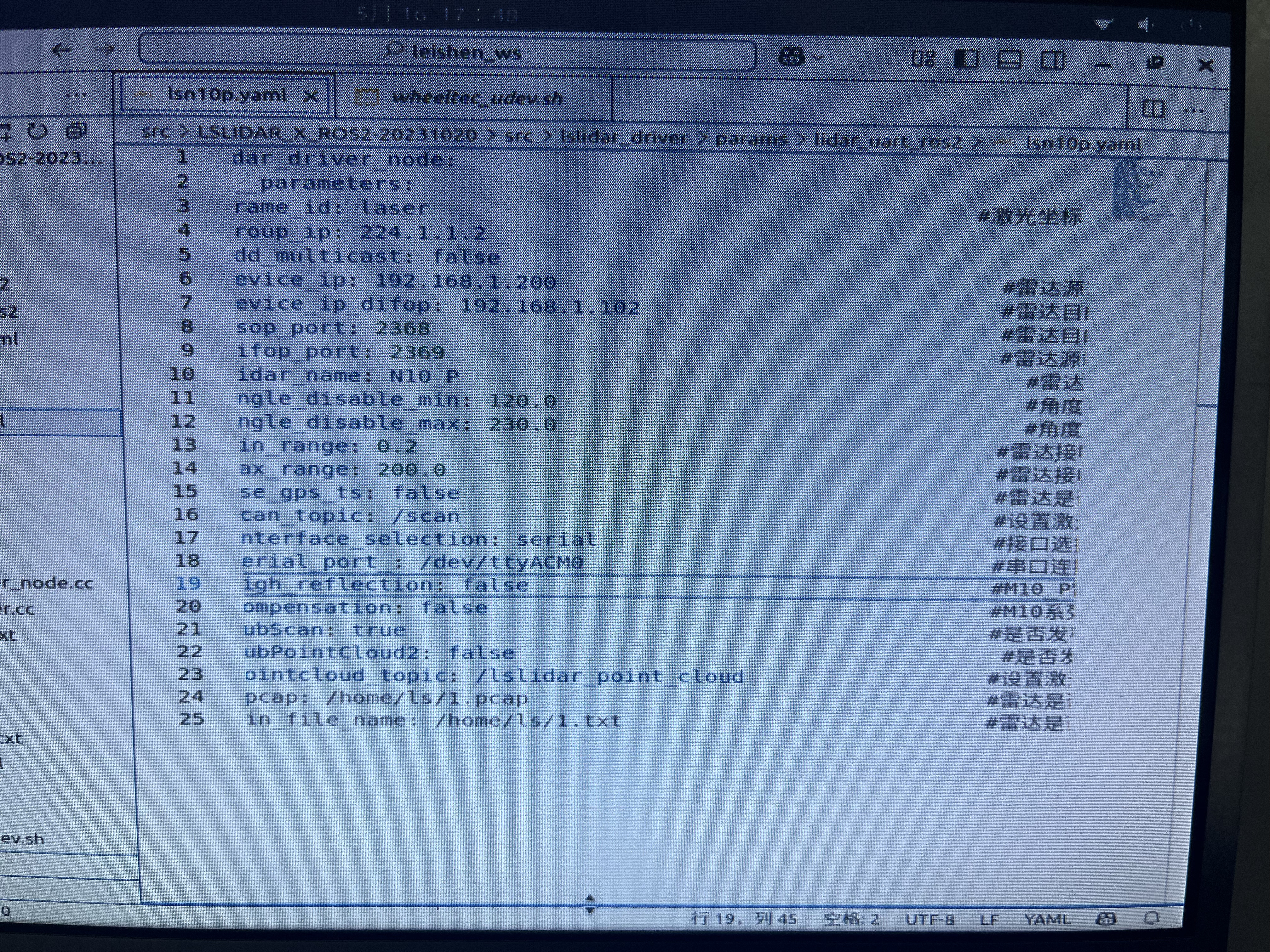 看懂这个参数可以看一下ros2的激光雷达的消息接口都有一些什么消息:Sensor_msgs/msg/LaserScan 这个接口
ros2 interface show sensor_msgs/msg/LaserScan返回
# Single scan from a planar laser range-finder
#
# If you have another ranging device with different behavior (e.g. a sonar
# array), please find or create a different message, since applications
# will make fairly laser-specific assumptions about this data

std_msgs/Header header # timestamp in the header is the acquisition time of
	builtin_interfaces/Time stamp
		int32 sec
		uint32 nanosec
		string frame_id
                             # the first ray in the scan.
                             #
                             # in frame frame_id, angles are measured around
                             # the positive Z axis (counterclockwise, if Z is up)
                             # with zero angle being forward along the x axis

float32 angle_min            # start angle of the scan [rad]
float32 angle_max            # end angle of the scan [rad]
float32 angle_increment      # angular distance between measurements [rad]

float32 time_increment       # time between measurements [seconds] - if your scanner
                             # is moving, this will be used in interpolating position
                             # of 3d points
float32 scan_time            # time between scans [seconds]

float32 range_min            # minimum range value [m]
float32 range_max            # maximum range value [m]

float32[] ranges             # range data [m]
                             # (Note: values < range_min or > range_max should be discarded)
float32[] intensities        # intensity data [device-specific units].  If your
                             # device does not provide intensities, please leave
                             # the array empty.
这里我直接引用了一篇ROS2+cartorgrapher+激光雷达建图并保存_cartographer ros2-CSDN博客这个文章的细节,我不过多赘述
消息头有三部分的数据,int32 sec,uint32 nanosec,string frame_id
sec和nanosec就是时间戳,代表着发布消息的秒和纳秒。
frame_id 是消息中与数据相关联的参考系id,例如在在激光数据中,frame_id对应激光数据采集的参考系(坐标系)。
frame_id是就是某一物体的参考系的坐标名字
其次是ROS的坐标系统
常见的坐标系
在使用ROS进行定位导航等操作时,我们经常会遇到各种坐标系。每种坐标系都有明确的含义。理论上坐标系的名称可以是随意的,但是为了方便不同的软件间共享坐标信息,ROS定义了几个常见的坐标系。

1.base_link
base_link坐标系和机器人的底盘直接连接。其具体位置和方向都是任意的。对于不同的机器人平台,底盘上会有不同的参考点。不过ROS也给了推荐的坐标系取法。

x 轴指向机器人前方
y 轴指向机器人左方
z 轴指向机器人上方

2.odom
odom是一个固定在环境中的坐标系也就是world-fixed。它的原点和方向不会随着机器人运动而改变。但是odom的位置可以随着机器人的运动漂移。漂移导致odom不是一个很有用的长期的全局坐标。然而机器人的odom坐标必须保证是连续变化的。也就是在odom坐标系下机器人的位置必须是连续变化的,不能有突变和跳跃。
在一般使用中odom坐标系是通过里程计信息计算出来的。比如轮子的编码器或者视觉里程计算法或者陀螺仪和加速度计。odom是一个短期的局域的精确坐标系。但是却是一个比较差的长期大范围坐标。

3.map
map和odom一样是一个固定在环境中的世界坐标系。map的z轴是向上的。机器人在map坐标系下的坐标不应该随着时间漂移。但是map坐标系下的坐标并不需要保证连续性。也就是说在map坐标系下机器人的坐标可以在任何时间发生跳跃变化。
一般来说map坐标系的坐标是通过传感器的信息不断的计算更新而来。比如激光雷达,视觉定位等等。因此能够有效的减少累积误差,但是也导致每次坐标更新可能会产生跳跃。
map坐标系是一个很有用的长期全局坐标系。但是由于坐标会跳跃改变,这是一个比较差的局部坐标系(不适合用于避障和局部操作)。

坐标系的约定
在非结构化的环境中(比如开放环境),如果我们要定义一个全球坐标系

默认的方向要采用 x轴向东,y轴向北,z轴向上
如果没有特殊说明的话z轴为零的地方应该在WGS84椭球上(WGS84椭球是一个全球定位坐标。大致上也就是z代表水平面高度)
如果在开发中这个约定不能完全保证,也要求尽量满足。比如对于没有GPS,指南针等传感器的机器人,仍然可以保证坐标系z轴向上的约定。如果有指南针传感器,这样就能保证x和y轴的初始化方向。
在结构化的环境中(比如室内),在定义坐标系时和环境保持对应更有用。比如对于有平面图的建筑,坐标系可以和平面图对应。类似的对于室内环境地图可以和建筑物的层相对应。对于有多层结构的建筑物,对每一层单独有一个坐标系也是合理的。

4.earth
这个坐标系是为了多个机器人相互交互而设计的。当有多个机器人的时候,每个机器人都有自己的map坐标系,他们之间的map坐标系并不相同。如果想要在不同的机器人间共享数据,则需要这个坐标系来进行转化。
如果map坐标系是一个全局坐标系,那么map到earth坐标系的变化可以是一个静态变换。如果不是的话,就要每次计算map坐标系的原点和方向。
在刚启动的时候map坐标系的全局位置可能是不知道的。这时候可以先不发布到earth的变换,直到有了比较精确的全局位置。

坐标系之间的关系
坐标系之间的关系可以用树图的方式表示。每一个坐标系只能有一个父坐标系和任意多个子坐标系。

earth -> map -> odom -> base_link
按照之前的说明,odom和map都应该连接到base_link坐标系。但是这样是不允许的,因为每一个坐标系只能有一个父坐标系。

额外的中间坐标系
这个图只表示了最少的坐标系。在保证基本的结构不变的情况下可以在其中加入中间的坐标系以提供额外的功能。

多机器人坐标系的例子

earth --> map_1 --> odom_1 --> base_link1
earth --> map_2 --> odom_2 --> base_link2

坐标系变换的计算
odom到base_link的变换由里程计数据源中的一个发布

map到base_link通过定位组件计算得出。但是定位组件并不发布从map到base_link的变换。它首先获取odom到base_link的变换然后利用定位信息计算出map到odom的变换。

earth到map的变换是根据map坐标系选取所发布的一个静态变换。如果没有设置,那么就会使用机器人的初始位置作为坐标原点。

Map之间的切换
如果机器人的运动范围很大,那么极有可能是要切换地图的。在室内环境下,在不同的建筑物中,和不同的楼层地图都会不同。
在不同的地图间切换的时候,定位组件要恰当的把odom的parent替换成新的地图。主要是map到base_link之间的变换要选取恰当的地图,然后在转换成map到odom之间的变换。

odom坐标系的连续性
在切换地图的时候,odom坐标系不应该受到影响。odom坐标系要保证连续性。可能影响连续性的情况包括进出电梯,机器人自身没有运动,但是周围环境发生很大的变化。还有可能由于运动距离太远,造成数据溢出。这些都要特殊进行处理。引用自ROS坐标系统,常见的坐标系和其含义 | 蓝鲸ROS机器人论坛
cartographer建图过程
想用cartographer建图只需要修改cartographer_ros中的两个文件
1.找到bcakpack2d.lua,它在/opt/ros/humble/share/cartographer_ros/configuration_files下
首先要给opt整个文件夹读写权限(后续第一次建图关掉终端可能要再给一次,因为它生成的有一个文件会默认被锁上)
sudo chown -R username /opt打开backpack2d.lua文件,将其中的内容换成自己的 frame部分全换成自己雷达的id下面是根据官方给的改好的,直接换个frame就ok,加imu的话另讲
include "map_builder.lua"
include "trajectory_builder.lua"

options = {
  map_builder = MAP_BUILDER,
  trajectory_builder = TRAJECTORY_BUILDER,
  map_frame = "map",
  tracking_frame = "laser",
  published_frame = "laser",
  odom_frame = "odom",
  provide_odom_frame = false,
  publish_frame_projected_to_2d = false,
  use_pose_extrapolator = false,
  use_odometry = false,
  use_nav_sat = false,
  use_landmarks = false,
  num_laser_scans = 1,
  num_multi_echo_laser_scans = 0,
  num_subdivisions_per_laser_scan = 1,
  num_point_clouds = 0,
  lookup_transform_timeout_sec = 0.2,
  submap_publish_period_sec = 0.3,
  pose_publish_period_sec = 5e-3,
  trajectory_publish_period_sec = 30e-3,
  rangefinder_sampling_ratio = 1.,
  odometry_sampling_ratio = 1.,
  fixed_frame_pose_sampling_ratio = 1.,
  imu_sampling_ratio = 1.,
  landmarks_sampling_ratio = 1.,
}

MAP_BUILDER.use_trajectory_builder_2d = true

TRAJECTORY_BUILDER_2D.submaps.num_range_data = 35
TRAJECTORY_BUILDER_2D.min_range = 0.
TRAJECTORY_BUILDER_2D.max_range = 200.
TRAJECTORY_BUILDER_2D.missing_data_ray_length = 5.
TRAJECTORY_BUILDER_2D.use_imu_data = false
TRAJECTORY_BUILDER_2D.use_online_correlative_scan_matching = true
TRAJECTORY_BUILDER_2D.real_time_correlative_scan_matcher.linear_search_window = 0.1
TRAJECTORY_BUILDER_2D.real_time_correlative_scan_matcher.translation_delta_cost_weight = 10.
TRAJECTORY_BUILDER_2D.real_time_correlative_scan_matcher.rotation_delta_cost_weight = 1e-1

POSE_GRAPH.optimization_problem.huber_scale = 1e2
POSE_GRAPH.optimize_every_n_nodes = 35
POSE_GRAPH.constraint_builder.min_score = 0.65

return options
然后改backpack_2d.launch.py这个文件,它在/opt/ros/humble/share/cartographer_ros/launch下,下面也是改好的,将.lua文件和launch.py这两个文件全部重命名为mylaser.lua和mylaser.launch.py,出处在ROS2+cartographer+镭神N10_P激光雷达建图_n10p激光雷达-CSDN博客这篇文章
"""
  Copyright 2018 The Cartographer Authors
  Copyright 2022 Wyca Robotics (for the ros2 conversion)

  Licensed under the Apache License, Version 2.0 (the "License");
  you may not use this file except in compliance with the License.
  You may obtain a copy of the License at

       http://www.apache.org/licenses/LICENSE-2.0

  Unless required by applicable law or agreed to in writing, software
  distributed under the License is distributed on an "AS IS" BASIS,
  WITHOUT WARRANTIES OR CONDITIONS OF ANY KIND, either express or implied.
  See the License for the specific language governing permissions and
  limitations under the License.
"""

from launch import LaunchDescription
from launch.actions import DeclareLaunchArgument, IncludeLaunchDescription
from launch.conditions import IfCondition, UnlessCondition
from launch.substitutions import LaunchConfiguration
from launch_ros.actions import Node, SetRemap
from launch_ros.substitutions import FindPackageShare
from launch.launch_description_sources import PythonLaunchDescriptionSource
import os

def generate_launch_description():

    ## ***** Launch arguments *****
    use_sim_time_arg = DeclareLaunchArgument('use_sim_time', default_value = 'False')

    ## ***** File paths ******
    pkg_share = FindPackageShare('cartographer_ros').find('cartographer_ros')
   # urdf_dir = os.path.join(pkg_share, 'urdf')
   # urdf_file = os.path.join(urdf_dir, 'backpack_2d.urdf')
   # with open(urdf_file, 'r') as infp:
   #     robot_desc = infp.read()

    ## ***** Nodes *****
   # robot_state_publisher_node = Node(
   #     package = 'robot_state_publisher',
   #     executable = 'robot_state_publisher',
   #     parameters=[
   #         {'robot_description': robot_desc},
   #         {'use_sim_time': LaunchConfiguration('use_sim_time')}],
   #     output = 'screen'
   #     )

    cartographer_node = Node(
        package = 'cartographer_ros',
        executable = 'cartographer_node',
        arguments = [
            '-configuration_directory', FindPackageShare('cartographer_ros').find('cartographer_ros') + '/configuration_files',
            '-configuration_basename', 'mylaser.lua'],
        remappings = [
            ('scan', 'scan')],
        output = 'screen'
        )

    cartographer_occupancy_grid_node = Node(
        package = 'cartographer_ros',
        executable = 'cartographer_occupancy_grid_node',
        parameters = [
            {'use_sim_time': False},
            {'resolution': 0.05}],
        )

    rviz_node = Node(
        package='rviz2',
        namespace='rviz2',
        executable='rviz2',
        name='rviz2',
        output='screen')
    return LaunchDescription([
        use_sim_time_arg,
        # Nodes
       # robot_state_publisher_node,
        rviz_node,
        cartographer_node,
        cartographer_occupancy_grid_node,
    ])
修改好后去安装rqt去查看节点状态
sudo apt update
sudo apt install ros-humble-rqt*
# 运行
rqt_graph
安装地图管理功能包
udo apt install ros-humble-nav2-map-server这里要先让激光雷达先运行启动再运行cartographer
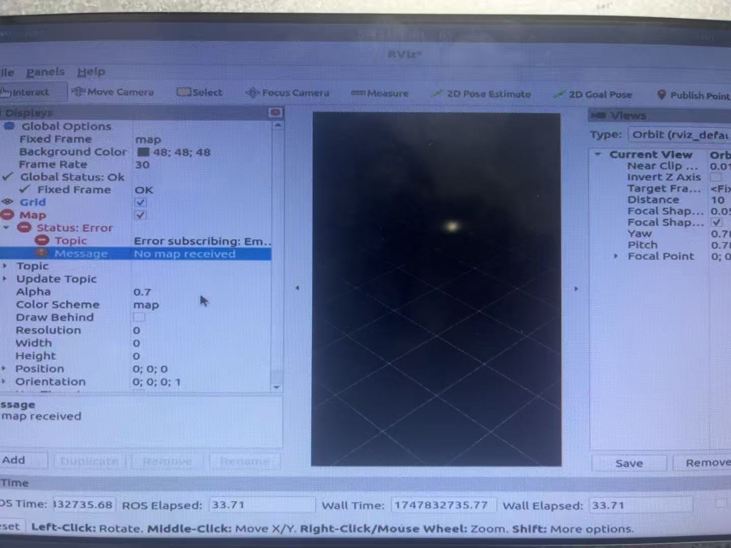
ros2 launch lslidar_driver lsn10p_launch.py 运行激光雷达ros2 launch cartographer_ros mylaser.launch.py这里最开始可能会出现建不出来图的问题
我们去找左下角的add
添加Map图
并且在topic中输入/map
OK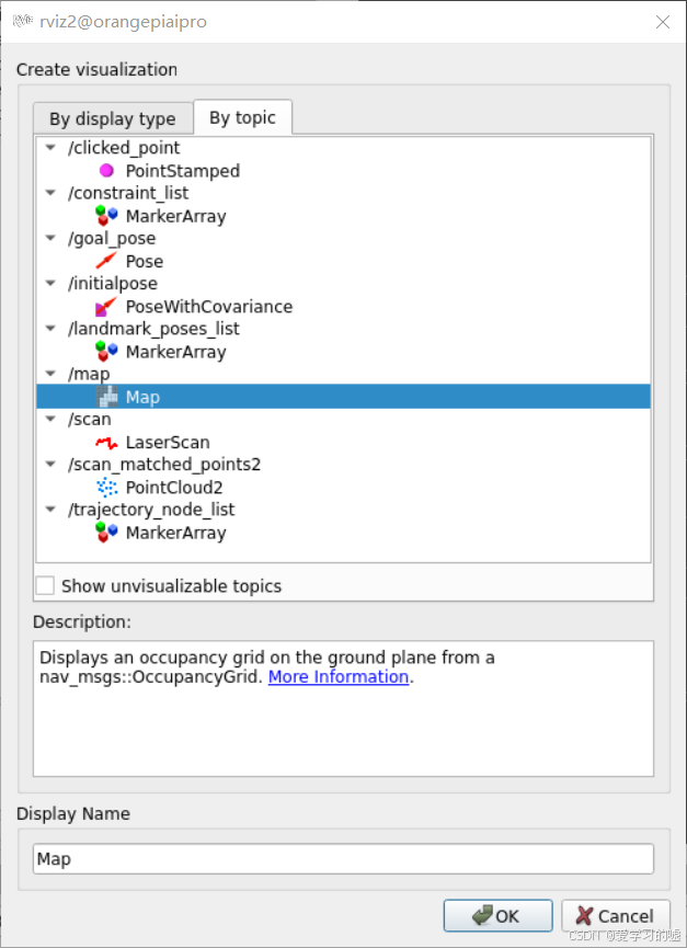
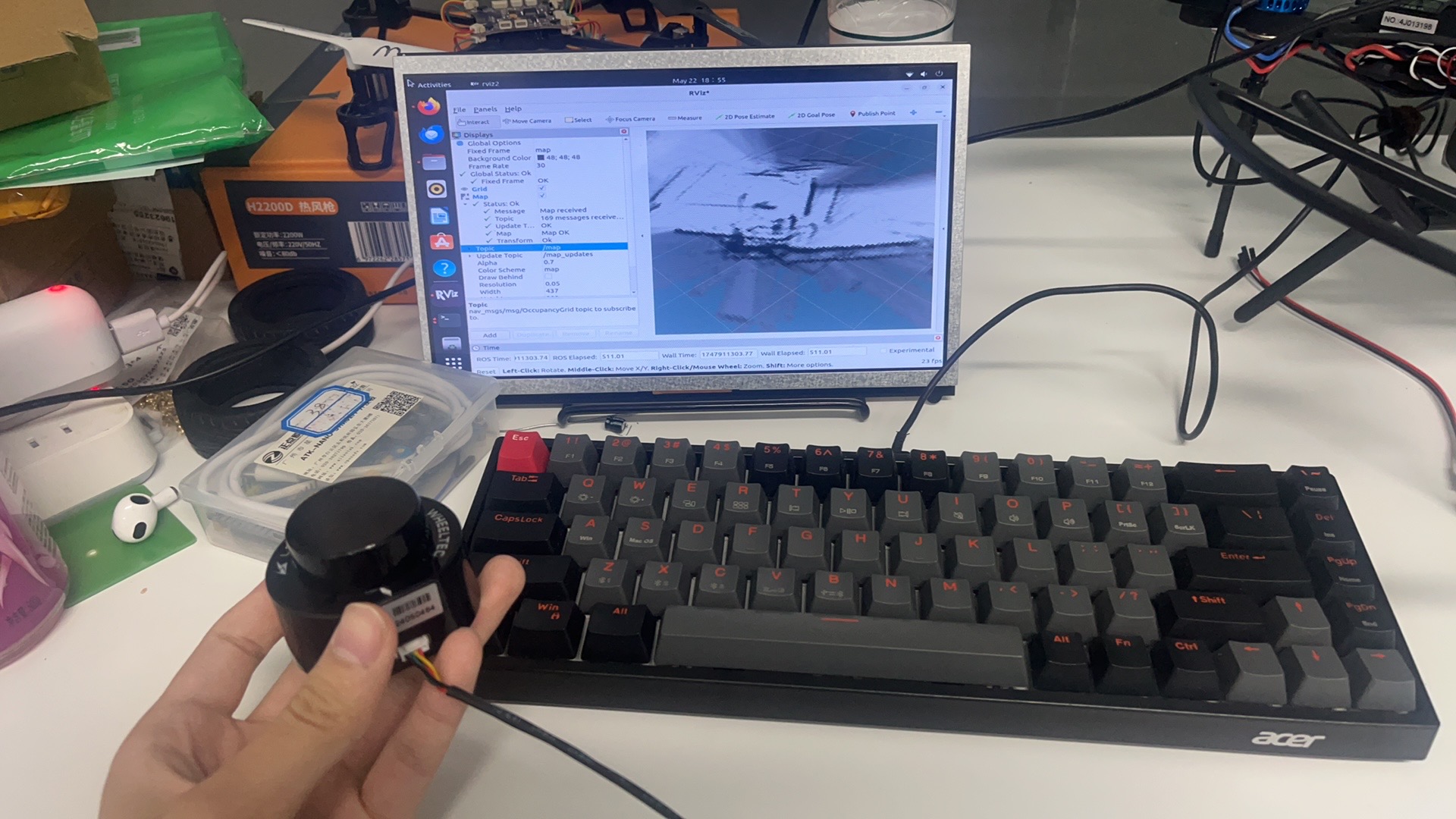
然后就可以看到能够成功建图了
可能会有一点我不确定的小问题
如果还建不成图的话去找cartographer中的rviz文件,将其复制到激光雷达(也就是我们的工作区中的rviz文件夹中再重新编译建图)
colcon build